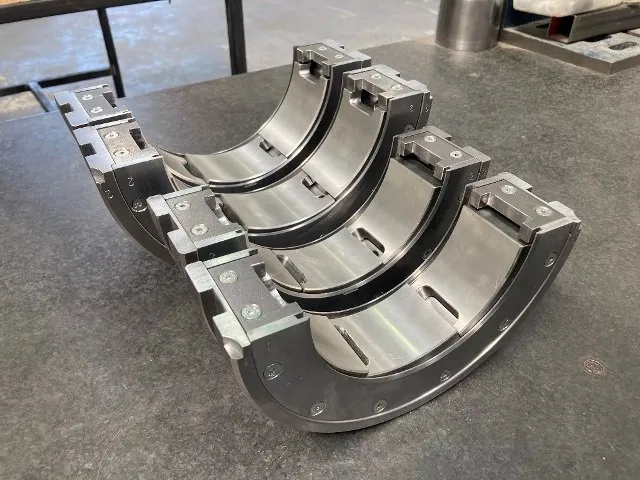
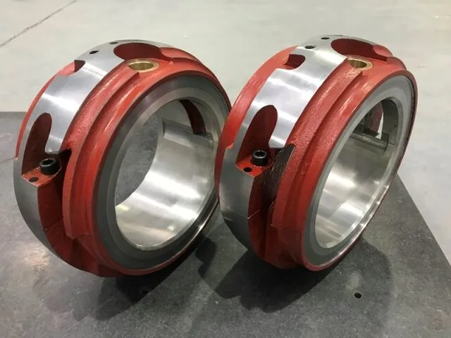
| Running geometry | One stationary cylindrical or profiled bore. | Several pads rotate independently through small angles about their pivots. |
| Oil-wedge formation | Created mainly by shaft eccentricity inside the fixed clearance profile. | Each pad changes attitude to establish its own converging film. |
| Dynamic cross-coupling | Can produce significant cross-coupled stiffness, particularly in lightly loaded, high-speed service. Profile changes and grooves can improve stability. | Normally much lower because pad motion allows the film force to follow shaft position more directly. It should not be assumed to be exactly zero. |
| Rotor stability | Suitable where analysis confirms adequate stability margin; oil whirl or oil whip can limit some high-speed, lightly loaded applications. | Often selected for high-speed turbomachinery where control of oil-film instability is a primary requirement. |
| Load direction | Performance can be sensitive to load angle and to the position of grooves, lobes and reliefs. | Can accommodate varying load direction more readily, although load-on-pad and load-between-pad orientation still affect performance. |
| Alignment response | A continuous fixed bore requires shaft, housing and bearing geometry to be well aligned to avoid edge loading. | Independent pads and suitable pivots can accommodate limited local misalignment, but they do not correct machine alignment errors. |
| Mechanical complexity | Fewer components, no pad pivots and generally simpler manufacture, assembly and inspection. | More parts and controlled features, including pads, pivots, retainers, carrier geometry and instrumentation routes. |
| Direction of rotation | Symmetric profiles can support either direction; oil grooves and asymmetric features must still be checked. | Centre-pivot designs may be bidirectional. Offset pivots and directed lubrication are commonly rotation-specific. |
| Design variables | Clearance, L/D ratio, bore profile, groove location, material and lubrication method. | All relevant clearances plus pad count, arc, preload, pivot type, pivot offset, load orientation and pad flexibility. |
| Typical use | Pumps, motors, gearboxes, fans and turbines where load, speed and stability permit a fixed geometry. | Compressors, turbines and other high-speed or stability-critical rotating machinery. |