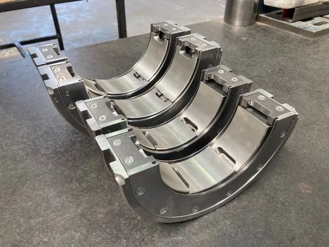
Instrumented tilting-pad journal bearing installed in a steam turbine

Bearing Temperature Sensors

How to select, position, install and test RTDs and thermocouples in fluid-film journal and thrust bearings.

A Bearing Sensor Measures One Location, Not the Whole Oil Film

An embedded RTD or thermocouple reports temperature at its sensing element. The value depends on circumferential or radial position, axial position, depth below the running surface, thermal contact, backing material and response time. A sensor can provide effective alarm and trend protection only when its exact installation and the associated limits are known.

Sensor type, location, depth, pad identity, rotation direction, wiring and alarm logic belong on the controlled bearing and instrumentation drawings.

Measurement Chain

Every Link Can Change the Reading

1

Oil Film and Metal

Local heat is generated and conducted into the lining and backing.

2

Sensing Element

The RTD or thermocouple responds at one installed position.

3

Leads and Junctions

Wire resistance, polarity, shielding and terminations affect the signal.

4

Monitor and Logic

The input converts, displays, trends, alarms and trips from the signal.

A loop simulation can prove stages 3 and 4 from the injection point onward. It does not prove element accuracy, installation contact or placement in stages 1 and 2.

Sensor Types

RTD or Thermocouple?

Both can protect bearings when the complete sensor and monitoring system is correctly specified.

Resistance measurement

RTD

A resistance temperature detector changes electrical resistance with temperature. Platinum Pt100 elements are common in industrial bearing monitoring.

  • Good stability and repeatability
  • Near-linear response over bearing temperatures
  • Two-, three- or four-wire measurement
  • Single or dual sensing elements
Thermoelectric voltage

Thermocouple

Two dissimilar conductors generate a small voltage related to the temperature difference between sensing and reference junctions.

  • Small sensing junction and fast response
  • Rugged and simple element construction
  • Letter type, polarity and cable must match
  • Requires cold-junction compensation
FactorPlatinum RTDThermocouple
Primary signalResistance in ohmsSmall EMF in millivolts
Common bearing formsPt100; two-, three- or four-wire; single or dual elementSpecified letter type such as J, K or T; grounded or ungrounded junction
Useful characteristicsStable, repeatable and well suited to normal bearing-metal temperature rangesCompact, rugged, responsive and tolerant of a broad temperature range
Important errorsLead resistance, wrong element curve, self-heating, damaged insulation or poor thermal contactWrong type, reversed polarity, incorrect extension cable, parasitic junctions, noise or cold-junction error
Basic electrical checkElement resistance, lead balance and insulation where applicableContinuity, polarity and insulation only for an ungrounded junction
True sensor calibrationControlled temperature source plus resistance measurement and reference thermometerControlled source plus EMF measurement with defined reference-junction compensation

RTD Wiring

Lead Compensation Changes the Measurement

2-wire

Element Plus Lead Resistance

Both lead resistances add directly to the indicated value unless compensated elsewhere. Suitable only where the specified error remains acceptable.

3-wire

Instrument Compensation

The monitor estimates lead resistance, normally assuming the matching leads have similar resistance. Unequal leads introduce residual error.

4-wire

Separate Sense and Excitation

Kelvin measurement largely removes lead resistance from the result when connected to a compatible four-wire input.

Pt100 reference

A Pt100 has nominal resistance of 100 Ω at 0°C. An IEC 60751 element with the common 0.00385 coefficient is approximately 109.7 Ω at 25°C, before two-wire lead resistance. Confirm the actual element curve and measured temperature.

Sensor Placement

Position for the Failure Mode and Load Case

The approved OEM or bearing drawing takes precedence. These locations explain common practice, not universal drilling dimensions.

Fixed-profile journal

Loaded Zone and Axial Spread

Place the element in the predicted high-temperature loaded region. Where shaft or housing misalignment can cause edge loading, sensors near both axial ends can reveal a temperature split that one centreline sensor would miss.

Tilting-pad journal

Loaded Pad, Downstream Region

A common location is in the loaded pad toward the trailing-edge high-temperature region, often around 75% of pad arc from its leading edge. Axial centreline suits some self-aligning pads; edge sensors may be required for non-aligning pads.

75 / 75
Tilting-pad thrust

Define 75/75 From Rotation

For unidirectional service, 75/75 commonly means 75% of circumferential length from the leading edge and 75% of radial width outward from the inner diameter. Bidirectional bearings require a different position defined by the drawing.

Depth: a deeper sensor usually reads lower and responds more slowly. Field sensors are commonly fitted in the backing just beneath the lining; laboratory research may embed very small elements closer to the working surface.

Coverage: one sensor reports one location. Multiple pads, dual elements or axial pairs may be needed to detect unequal load sharing, reverse rotation or edge loading.

Rotation: leading and trailing edges reverse when shaft direction changes. Offset pivots, oil feeds and sensor positions must be reviewed for every permitted direction.

Physical Installation

The Mounting Method Is Part of the Measurement

01

Controlled Hole and Contact

Machine the diameter, depth and flat-bottom geometry specified for the sensor case. Spring loading, a retaining ring or qualified potting can maintain contact and permit replacement.

02

Protect the Running Surface

Do not distort or break through the finished lining. Remove burrs and swarf, then verify the remaining depth to the running surface against the drawing.

03

Route and Retain Leads

Use controlled grooves and bend radii. Keep leads clear of pads, pivots, split faces and rotating parts, and prevent fretting against sharp housing edges.

04

Seal the Oil Path

Prevent lubricant tracking along leads or braid through the housing feedthrough. The sealing method must suit oil, temperature, pressure and hazardous-area requirements.

05

Control Grounding

Specify grounded or isolated construction. Insulated bearings may require electrically isolated sensors so instrumentation does not create an uncontrolled shaft-current path.

06

Identify Every Channel

Mark bearing side, pad number, element A/B, sensor type, wire configuration, location and rotation reference at both bearing and panel terminations.

Minimum Specification

Information Needed Before Manufacture

Element

RTD material, nominal resistance, coefficient and accuracy class; or thermocouple type, tolerance and grounded/ungrounded junction.

Circuit

Two-, three- or four-wire RTD; single or dual element; thermocouple polarity; shield termination and isolation requirements.

Location

Pad or shell identity, circumferential/radial and axial coordinates, depth, rotation direction and drawing datum.

Lead System

Insulation, braid, cable length, bend radius, oil blocking, extension cable, feedthrough, connector and terminal box.

Environment

Temperature, vibration, oil chemistry, ingress, EMC, electrical isolation and hazardous-area certification.

Acceptance

Continuity, insulation, calibration or response test, documentation, channel identification and as-built resistance values.

Testing RTDs and Thermocouples

Isolate First, Then Prove One Boundary at a Time

Only trained personnel should test protection circuits. Follow the machine isolation procedure and prevent an unintended trip, start or loss of protection.

Disconnect the sensor from monitoring electronics before resistance or insulation measurements. Do not apply a high-voltage insulation tester unless the sensor, cable, barriers and connected equipment are specifically approved for that test.

RTD check

Resistance Temperature Detector

  1. Identify: confirm Pt100 or other element, wire count, single/dual circuit and terminal diagram.
  2. Inspect: check crushed insulation, frayed braid, oil ingress, loose joints and sharp lead exits.
  3. Measure: record element resistance and lead-pair resistance with the sensor at a measured, stable temperature.
  4. Compare: use the correct IEC 60751 or manufacturer resistance-temperature table, including lead resistance for two-wire circuits.
  5. Insulation: where the construction permits, test each circuit to the case, braid or bearing using the manufacturer's method and limit.
  6. Calibrate if required: use a controlled bath or dry block and calibrated reference, recording several increasing and decreasing temperature points.
Thermocouple check

Thermocouple

  1. Identify: confirm letter type, polarity, junction grounding, cable type and cold-junction arrangement.
  2. Inspect: check lead and braid damage, oil wicking, connector alloy, terminal material and unintended junctions.
  3. Continuity: isolate the circuit and check for an open or abnormal resistance against the sensor manufacturer's data.
  4. Insulation: test only an ungrounded construction. A grounded junction is intentionally connected to its case.
  5. Response: apply a controlled temperature and verify millivolt polarity and magnitude using matching thermocouple connections and correct reference-junction compensation.
  6. Calibrate if required: compare the sensor with a calibrated reference through the required range and acceptance tolerance.
Level 1

Electrical Health

Continuity, resistance balance, insulation and visual condition find opens, shorts and damaged leads. They do not prove temperature accuracy.

Level 2

Sensor Response

Controlled heating with a reference checks that the element responds correctly. An installed bearing may have gradients that limit calibration accuracy.

Level 3

Loop Simulation

A calibrated resistance or millivolt source checks transmitter scaling, display, alarms, trips and logic. It bypasses the physical sensor.

Level 4

End-to-End Proof

A documented test combines sensor evidence, wiring checks, channel identity, monitor response and alarm/trip action under controlled conditions.

Fault Patterns

What an Abnormal Reading May Mean

Observed symptomPossible sensor or circuit causeMechanical condition to exclude
Sudden open-circuit or upscale indicationBroken element, lead or terminal; input burnout directionConfirm no actual rapid over-temperature event occurred first
Implausibly low or fixed readingShorted leads, wrong input type, failed transmitter or poor thermal contactLow load, cold oil, unloaded pad or changed operating condition
One channel consistently offsetWrong RTD curve, lead resistance, thermocouple type/polarity, junction or calibration errorReal pad load imbalance, misalignment, oil distribution or sensor-position difference
Noisy or intermittent trendLoose terminal, damaged braid, ground loop, EMI, fretting lead or moisture ingressActual vibration, pad flutter, unstable oil supply or transient load
Axial pair divergesDifferent depths, swapped channels or damaged elementEdge loading, shaft slope, housing distortion or uneven clearance
All pads rise togetherCommon reference, input or scaling faultHigh inlet temperature, low flow, viscosity loss, speed or load change

Common Questions

Bearing Sensor FAQ

Is an RTD better than a thermocouple?

Not universally. Pt100 RTDs offer stable, repeatable measurement; thermocouples are compact and rugged. The input system, response, wiring, vibration, certification and redundancy requirements decide.

Where is the hottest point?

It depends on bearing geometry, load, speed, oil supply and distortion. The maximum film or surface temperature may not occur at the embedded sensor. Use thermal analysis and approved drawing locations.

What does 75/75 mean?

For a unidirectional thrust pad it conventionally identifies 75% of pad length from the leading edge and 75% of radial width outward from the inner diameter. State the datums and rotation on the drawing.

Can resistance prove an RTD is calibrated?

A room-temperature resistance check can identify an open, short or gross error. Calibration requires known temperatures, a reference thermometer and comparison with the correct resistance curve.

Can a grounded thermocouple be insulation tested?

Not as an isolated element-to-case circuit: its junction is intentionally grounded. Confirm construction before interpreting continuity to the case.

Does a loop test check sensor placement?

No. It checks the circuit from the injection point onward. It cannot prove that the sensor is at the correct depth, on the correct pad or in good thermal contact.

Technical Basis

Sensor definitions and testing were cross-checked against IEC 60751:2022 for industrial platinum resistance sensors, IEC 60584-1:2013 for thermocouple EMF and tolerances, Minco's bearing temperature sensor replacement criteria and spring-and-ring installation guidance, and Fluke's RTD calibration procedure. Placement was cross-checked against Kingsbury guidance on fluid-film bearing temperature measurement and tilting-pad temperature patterns. The bearing drawing, sensor manufacturer and machinery protection specification govern each installation.

Need Instrumented Journal or Thrust Bearings?

Send the bearing drawing, rotation, load cases, sensor specification and monitoring-system details for an instrumentation review.