Supply / Inlet Oil
Sets the entering viscosity and cooling potential. It does not measure the loaded film or pad hot spot.

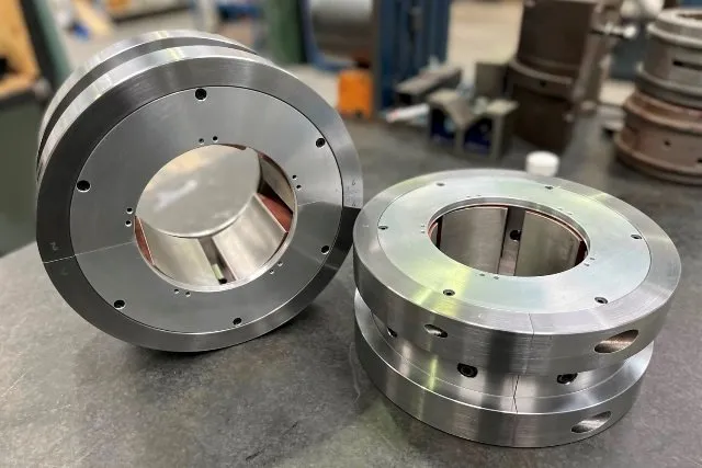
How to distinguish oil, metal and film temperatures before applying design, alarm or trip limits.
Typical industry practice limits maximum Babbitt operating temperature to 130°C (266°F) because bearing-alloy strength falls as temperature rises. A healthy bearing is normally designed and protected below that ceiling. The applicable drawing, machinery specification, OEM limit, alloy, load and sensor location can all require a lower value.
Every temperature value should identify the measured medium, sensor location and operating condition.
Sets the entering viscosity and cooling potential. It does not measure the loaded film or pad hot spot.
Useful for heat balance and overall temperature rise, but mixing can conceal one locally hot pad.
The usual protection measurement. Circumferential position, axial position and depth below the surface determine the reading.
Normally predicted by a thermal bearing model or specialised test instrumentation. It can be hotter than the embedded sensor indicates.
These values come from different products and guidance documents. They are not a universal alarm ladder.
| Published context | Temperature | How to use it |
|---|---|---|
| Typical industry maximum operating ceiling for Babbitt bearings, published by Waukesha Bearings | 130°C266°F | A material-related ceiling, not a normal design target or automatic trip value. Lower verified limits govern. |
| Maximum bearing-metal design criterion reported in a Texas A&M turbomachinery tutorial discussing API 617 | 100°C212°F | A design criterion reported for the referenced turbomachinery context. Confirm the applicable standard edition, equipment specification and measurement definition. |
| Normal design running guidance published for Kingsbury KN fixed-profile journal bearings | ≤115°C≤240°F | Product-specific guidance, useful only when the bearing type, measurement and duty are comparable. |
| Example alarm progression in the same Kingsbury KN guidance | Alarm: normal +8°CTrip: alarm +7°C; never above 130°C | An example of combining a stable operating baseline with an absolute ceiling. It is not a default for unrelated machines. |
| Kingsbury trigger for estimating thrust-bearing Babbitt temperature | Inlet oil >50°CAlso load >2.8 MPa or collar speed >76.2 m/s | An analysis trigger, not an inlet-temperature trip or bearing rating. |
The protection-system setpoints approved for the machine always take precedence over this reference table. Where no approved values exist, obtain bearing and rotor-system engineering review before setting them.
Use the dedicated bearing RTD and thermocouple guide for sensor selection, wiring, installation and testing procedures.
Published tilting-pad guidance commonly places a sensor on the loaded pad near the downstream high-temperature region, often around 75% of pad arc from the leading edge and near the axial centreline for self-aligning pads. Non-aligning pads may need sensors at more than one axial position to identify edge loading.
The 75/75 position is widely published for unidirectional tilting pads. Bidirectional arrangements may use a pivot-centred circumferential position, commonly described as 50/75. Multiple pads should be considered because load sharing and misalignment can create pad-to-pad temperature differences.
Depth matters: temperature gradients through the lining and backing can be steep. A sensor placed deeper in the backing normally reads lower and responds more slowly than one close to the running surface. Compare only equivalent installations.
A temperature that remains below an absolute maximum can still indicate a developing fault when its trend or pad-to-pad spread changes.
Record normal values after thermal stabilisation at known speed, load, inlet temperature, flow and machine configuration.
A rapid increase can require action before the steady-state alarm is reached. Account for sensor response lag and normal run-up transients.
Compare loaded pads and axial sensor pairs. Divergence can reveal unequal load sharing, misalignment, local starvation or a sensor problem.
Start with the machinery specification, OEM manual, approved bearing drawing, protection-system cause and effect, alloy and operating envelope.
Record sensor type, pad, angular and axial position, depth, units, calibration and whether the value is oil, metal or calculated surface temperature.
Trend stable readings over representative speed, load, inlet temperature and ambient conditions, including expected transients.
Choose an alert above expected variation but below the validated design and damage limits, considering sensor uncertainty and response delay.
Provide sufficient separation from alarm for response while remaining below the verified maximum for every credible operating condition.
Higher load, speed, load angle or changed process condition.
High inlet temperature, wrong viscosity, low flow, blocked feed or aeration.
Recirculated discharge oil entering the next pad or inadequate evacuation.
Incorrect clearance or preload, thermal growth, housing distortion or assembly error.
Edge loading, collar runout, shaft deflection or unequal thrust-pad loading.
Loose sensor, changed depth, wiring fault, calibration drift or channel mismatch.
Confirm the channel, sensor health, units and recent protection-system work.
Compare speed, load, inlet temperature, oil pressure, flow and vibration with the normal baseline.
Check other pads, drain temperature, axial sensor pairs and redundant measurements.
Review the rate of rise and follow the approved operating and trip procedure.
Retain trend data, oil samples, filter debris and inspection evidence for root-cause analysis.
Do not increase oil flow, clearance or setpoints without understanding the resulting film and rotor-dynamic effects.
No. It is a commonly published Babbitt maximum operating ceiling. Normal design, alarm and trip values are generally lower and specific to the machine and measurement.
No. Drain oil is mixed and can hide a local hot spot. It is useful for heat balance and trending but measures a different thermal condition.
Load sharing, alignment, pad position, sensor depth, calibration and local oil supply can all create a difference. The trend and installation must be reviewed together.
Not necessarily. Flow path, oil mixing, evacuation and churning matter. Any change should be checked against the bearing design rather than judged from flow quantity alone.
Published values and monitoring guidance were cross-checked against Waukesha Babbitt material guidance, Kingsbury thrust-bearing temperature guidance, Kingsbury fixed-profile journal-bearing data, and Texas A&M Turbomachinery Laboratory papers on modern journal-bearing performance, tilting-pad design and temperature measurement. Values are source-specific references, not Oiltech alarm or trip setpoints.
Send the bearing drawing, sensor locations, operating trends, oil data and machine conditions for an engineering assessment.